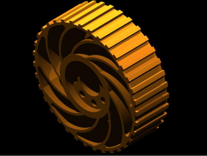
Update: Since posting this, I have found a project from 2017 that accomplishes the same thing, albeit on a much larger machine (a Shopbot, which is a large, commercially available CNC Router for cutting soft materials). The creators used a swiveling hot wheel, which is very cool. I think the ease and simplicity of my approach is noteworthy (see below), but take a look here for a very impressive CNC Heat sealer: https://cwandt.com/products/hscm
Scroll to the bottom for a long video of my machine in action
A consulting project needed a way to play around with different heat seal patterns for a soft, fluid heat exchanger made of a polyolefin film.
The conventional way to do this would be to machine a heat seal tool out of steel, heat it, and then adjust stamping pressure, temperature, and time to achieve the desired seal. Whether done as a DIY project, or sent to impulse heat sealing tool manufacturer, the iterative cycle time would be far too long.
It would probably work fine in this case to simply waterjet a stamp from steel. In theory, one could even 3D-print a stamp from a temperature-tolerant material and coat it with a conductive material for resistive heating. Either of those options are well-suited for creating a large number of duplicate heat seals, but are still far too slow if you want to try, say, 10 different patterns in a single afternoon.
A CNC heat sealer makes sense here. A fine, heated tip on the end of a motion gantry would allow for arbitrary patterns to be drawn as heat seals.
Since the requirements of this heat seal project were simple (3mm wide seal, in a forgiving material) I had the idea to repurpose an old filament-based 3D printer into a CNC heat sealer.
The basic premise is as follows: We already have a positioning system capable of moving at different speeds (the printer gantry) and a closed-loop heating device (the printer hot-end). Therefore we only need to do three things:
1 - Replace the heated nozzle with a heated indenter
2 - Add a mechanically compliant material to the print bed so that we are not crashing the gantry in the Z axis when applying heat-seal force
3 - Create a G-code program to turn the desired heat seal pattern into reality
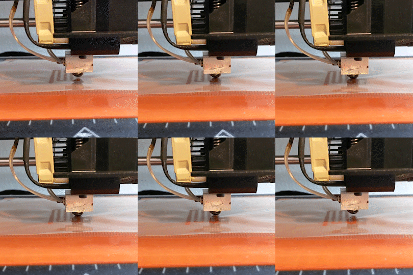
I machined a few different indenters to replace the nozzle before realizing that the nozzle could be modified by sanding the end with sandpaper until the flat sanded region was a circle with a diameter of 3 millimeters. This is very hacky, but it worked well. In theory, this means that the only strictly required hardware change to turn any FFF 3d printer into a CNC heat sealer is to sand down an old nozzle that you have laying around! If you were extremely time pressed, a short, M6 screw with a good head profile would probably work as well.
Next, I added a a sheet of 2mm heat resistant silicone rubber to the print bed. This allows the nozzle to overdrive into the plane of the heat seal without stalling the Z motor. This works fine, but has a notable downside: the material being heat sealed will concave down into the rubber, resulting in trapped stresses and dimensional inaccuracy. The correct way to do this is to add compliance in the Z axis to the nozzle, and rigidly hold the film to be sealed against a hard surface (e.g. the bare print bed). That said, this improper approach worked fine for a proof of concept, and the sticky rubber had the added benefit of helping the film to lay flat during the process. Since I shortened the nozzle by about 1 mm by sanding it, the existing Z-calibration of the printer would give 1mm of interference into the 2mm thick silicone. This worked well - but if it hadn’t, I could have used the four bed-leveling screws on the printer to lower or raise the bed. It is very forgiving!
The last step is the programming. If the heat seal tool had been some kind of metal wheel on a swivel (like the cutting tool on a vinyl cutter), then the gantry could trace continuous curves without moving in the Z axis. That is not what we have here however, so the movement process will be closer to what is known as “plunge milling” in the world of machining.
In plunge milling, a profile is machined by moving the cutting tool (drill bit, end mill, etc.) such that it is only ever drilling holes of various depths. Imagine cutting a square out of a piece of wood by following the marked lines with a hundred or so individually drilled holes. We can heat seal in the same way, creating the pattern through a sequence of plunge operations in spatial increments in the X and Y axes. While a few mm above the film, the nozzle is positioned over the location of the desired heat seal point, the nozzle drops down and creates the heat seal, then it lifts up. This is repeated for the whole pattern. This is labor intensive for a human, but easy for a stepper-driven gantry. It allows us to use the hardware we already have, and the software is very straight forward.
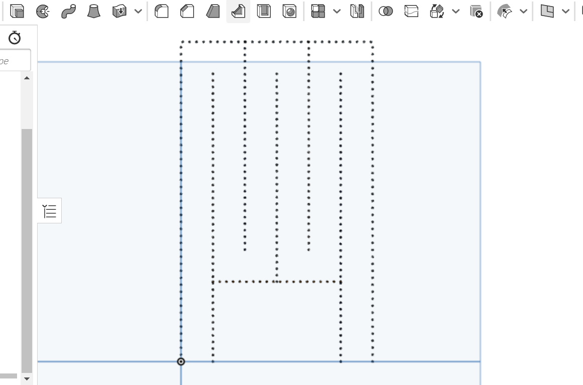
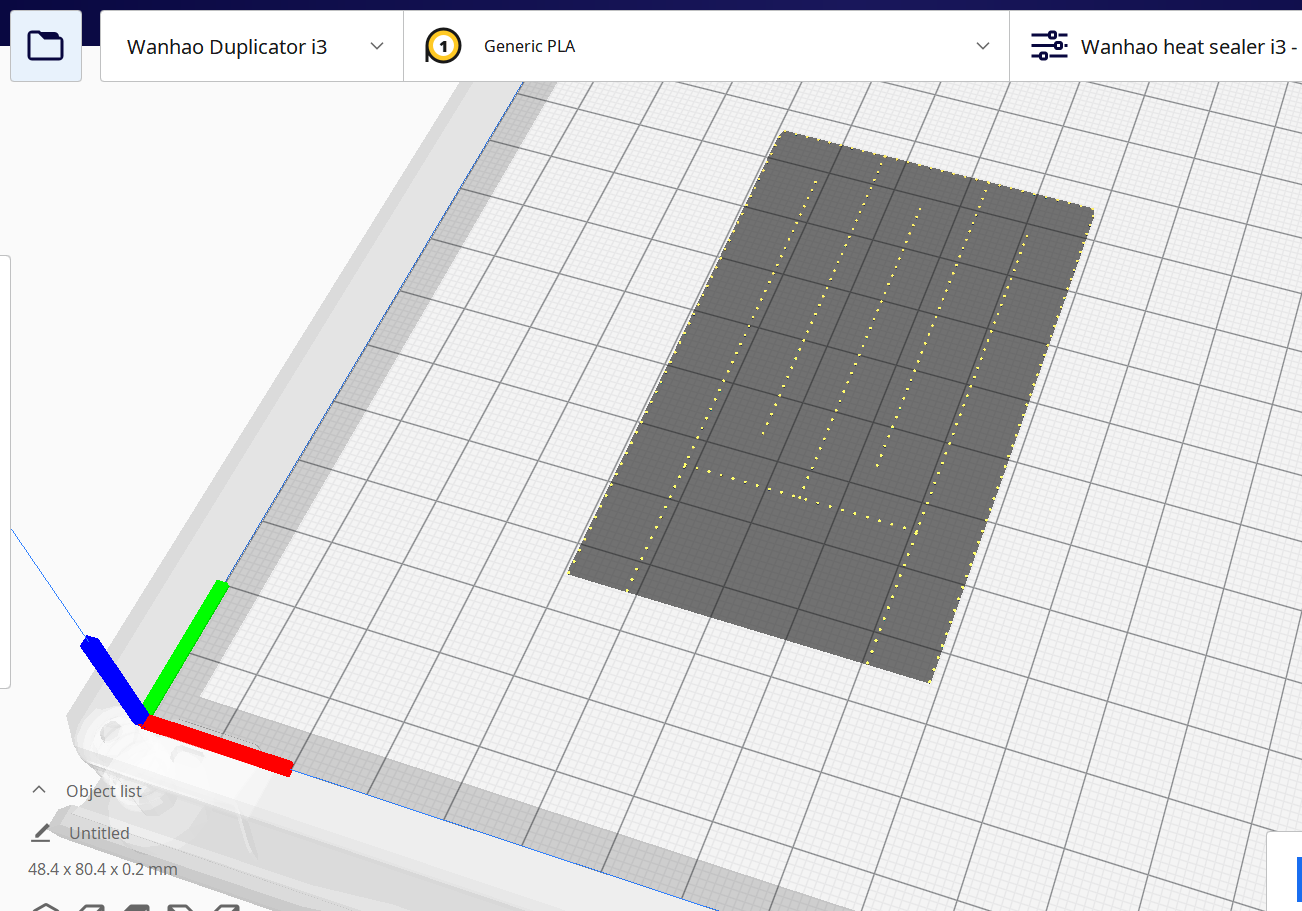
To try this out immediately, I created an STL that would trick a conventional 3D printing slicer software (Cura) into performing the required movements. I took the serpentine test pattern that I wanted to heat seal and used Onshape’s curve pattern tool to place a large number of 0.4mm diameter circles (“points”) along the test pattern. After exporting this as an STL file, it was a simple matter of configuring Cura to “print” each of these little blobs. There were 5 or so settings that had to be adjusted to make this work (i.e. walls, infill, G-code start block, etc.). I will forgo the detailed description of that here as I intend to convert this system to properly interpret a test DXF without the need for such a clunky software workflow.
The G-code has parameters for nozzle temperature, so I set it to the nominally recommended temperature for my file (“Foodsaver” heat seal vacuum bags). It only took a few attempts to dial in a great heat seal. Time, force (interference in Z), and temperature are the only knobs you really need to play with here, as long as the nozzle surface is flat and parallel to the print bed. As far as gantry speed goes - yes, it can likely go much faster, but the time per heat seal (in contact) times the number of individual sealed points is the dominant factor in how long an entire pattern takes. Shaving 1 minute off of a 17 minute process isn’t worth pushing this old gantry to its limits and skipping steps.
The final result was surprisingly good. With a few minutes of work on a computer, I could create any heat seal profile I want. Without any further development, I was able to test all five of the proposed heat seal patterns and send the prototypes to my client. Since I enjoyed this little side-project, I plan on refining it by:
Machining a better indenter, but give it the same thread as the printer nozzle so that it is an easy retrofit. The stretch goal will be to add compliance in Z to the part so that the soft silicone sheet is not required. This might be as simple as adding a spring to to the Z-motor mount.
Creating a slick software workflow that takes a vector drawing and generates the G-code automatically. The stretch goal will be to create a tuning script that sweeps heat seal parameters automatically so that new materials can be easily experimented with.


